
Wirebonding to PolyStrata®
Table of Contents
1. Overview
PolyStrata® components are commonly used in high-frequency and millimeter-wave assemblies where low-loss, broadband interconnects and compact three-dimensional structures are required. As these components are integrated onto target substrates and modules, reliable and repeatable wirebond transitions become a critical part of overall system performance. This application note provides guidance for assembly processes and expected post-attach performance when wirebonding to standard PolyStrata® RF launches.
1.1. Available Models and Usage
The following models are available by request to assist with design:
HFSS Models
- HFSS 3D-component of the PolyStrata launch for direct import
- Allows for simulating bond wires and target substrate
Recommended Wirebond Model
- Similar to the HFSS model above, but with example bonds and substrates included
- Includes example loop geometry and substrate designs for RO4350B, RT5880, and Alumina materials
Mechanical Model
- 3D STEP model of the full PolyStrata® part
- Used for mechanical form, fit, and function analysis in full system
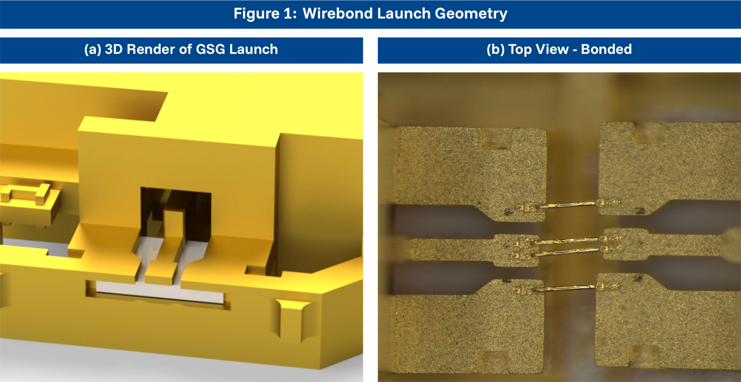
2. Wirebond Attach Process
This section outlines the recommended assembly practices for attaching wirebonds to PolyStrata® components. Although the PolyStrata® bond pads themselves are fabricated with gold surfaces optimized for ultrasonic bonding, proper surface preparation and controlled bonding parameters on the customer side are essential for achieving consistent mechanical strength and RF performance.
2.1. Overview of Wirebond Attach Process
- Argon plasma cleaning of both the PolyStrata® and target component’s wirebond interface
- Mechanical alignment and optical verification of alignment
- Gold wirebond attach
- Post-bond inspection, including optical inspection, pull tests, and electrical verification
2.2. Surface Preparation and Cleaning
Gold to gold wirebonding is sensitive to:
- Organic films from fingerprints, flux residue, etc.
- Oxide films on bond surface
- Moisture residue
- Particulates or other foreign debris
Even though PolyStrata® gold surfaces do not oxidize appreciably, foreign materials can inhibit weld formation and dramatically reduce bond pull strength. To mitigate this, argon plasma treatment is the preferred method for removing light organic contamination without chemically altering the PolyStrata® surface.
Argon Plasma Clean Steps
The below table outlines the recommended “recipe” for cleaning PolyStrata® components prior to bonding.
| Step Num. | Base Pressure (mT) | RF Power (W) | Argon (sccm) | Oxygen (sccm) | Time (s) |
|---|---|---|---|---|---|
| 1 | 225 | 400 | 0 | 210 | 240 |
| 2 | 60 | 300 | 25 | 0 | 90 |
| 3 | 60 | 200 | 25 | 0 | 600 |
Table: Cleaning Steps
2.3. Bonding Method Recommendations
PolyStrata® components are fully compatible with standard gold wedge or gold ball bonding methods. However, wedge is highly recommended due to better control of the wire loop parameters and its effect on RF performance.
Wire Type
- Material: Gold (Au), thermosonic compatible
- Diameter: 25.4µm round recommended
Bonding Method
Wedge bonding is highly preferred for PolyStrata® components due to:
- Lower bond loop height
- Better control of wire shape
- Lower inductance
Ball bonding can be used, but degradation in return loss and repeatability of the RF match is expected.
Ultrasonic Bond Parameters
- Bond force: 20–40 grams
- Bond time: 10–20 ms
- Stage temperature: 100–150°C
Loop Control
Loop parameters for wirebonding include horizontal gap, vertical offset between surfaces, and loop height. Generally, these parameters should be kept as small as possible to ensure a wideband RF match. However, consideration must be made for manufacturability. The table below provides a reference for maximum tolerable loop parameters for a 20dB return loss (typ.) match to a 5mil alumina substrate.
| Max. Frequency | Horizontal Gap (µm) | Vertical Offset (µm) | Loop Height (µm) |
|---|---|---|---|
| 85 GHz | ≤50 | ≤100 | ≤50 |
| 67 GHz | ≤75 | ≤100 | ≤50 |
| 50 GHz | ≤75 | ≤100 | ≤75 |
| 40 GHz | ≤100 | ≤100 | ≤75 |
| 30 GHz | ≤125 | ≤100 | ≤125 |
Table: Maximum Loop Parameters by Frequency
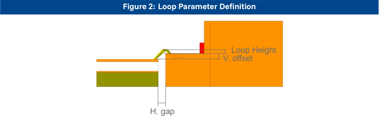
2.4. Avoiding Common Issues
Below is a list of common problems associated with improper wirebond assembly processes and recommended fixes.
| Issue | Cause | Recommended Fix |
|---|---|---|
| Weak pull strength | Organic contamination | Increase Ar plasma cleaning time and/or improve post clean handling controls |
| Poor heel geometry | Incorrect ultrasonic power | Tune US settings and verify tool condition |
| Wire sag | Excessive loop height or heat | Reduce loop height and decrease stage heating during bonding |
| Non-wet or “skipped” bonds | Hard Ni layer on target substrate | Reduce Ni thickness (ENIG/ENIPIG < 5 µm) |
| Lift-off under shock and vibration | Incorrect bond force | Slightly increase bond force within spec |
3. Wirebond Pull Tests and Performance
This section summarizes the mechanical and environmental performance of wirebonds attached to PolyStrata® components. To isolate the effects of assembly handling, substrate design, and the PolyStrata® surface condition, testing was conducted in two stages:
- Pre-bond testing: Components were first subjected to thermal and environmental stresses to assess surface stability prior to wirebond attachment.
- Post-bond testing: Following the initial environmental exposure, wirebonds were placed using the recommended thermosonic gold bonding process. Pull strength measurements were recorded to establish baseline mechanical performance.
This staged approach provides a clear view of how PolyStrata® surfaces, wirebond interface quality, and environmental stresses interact, and demonstrates the robustness of the wirebond attach process across the assembly lifecycle.
Wirebond Test Summary
| Number of Samples for Each Test | 16 components with 20 pulls performed per component |
| Pull Strength Pass/Fail Criteria | >3gf |
| Pull Angle | 90° |
| Wirebond Launch Angle | 45° from component surface |
| Pull Hook PN | HT-002-04121 |
| Pre-bond Test Result | All samples passed |
| Post-bond Test Result | All samples passed |
3.1. Pre-bond Testing
For this test group, parts were subjected to environmental stress prior to the wirebonding process.
| Description | Step 1 | Step 2 | Step 3 | Step 4 |
|---|---|---|---|---|
| 1 year storage profile | 85°C / 60% RH 168 hours | Plasma Clean | Wirebond | Pull Test |
| Epoxy curing cycle | 175°C – 4 hours in ambient humidity | Plasma Clean | Wirebond | Pull Test |
| SMT Reflow Cycle | 260°C – 6 minutes | Plasma Clean | Wirebond | Pull Test |
| All tests combined (sequential) | All pre-bond tests | Plasma Clean | Wirebond | Pull Test |
Table: Pre-bond Test Matrix
3.2. Post-bond Testing
This test group was subjected to environmental stresses after the wirebonding process.
| Description | Step 1 | Step 2 | Step 3 | Step 4 |
|---|---|---|---|---|
| Epoxy curing cycle | Plasma Clean | Wirebond | 175°C – 4 hours in ambient humidity | Pull Test |
| SMT Reflow Cycle | Plasma Clean | Wirebond | 260°C – 6 minutes | Pull Test |
| High-Temperature Stress | Plasma Clean | Wirebond | 300°C – 1hr in N₂ | Pull Test |
Table: Post-bond Test Matrix