
Nuvotronics PolyStrata® Power Combiners
Table of Contents
1. Introduction
This application note provides guidelines for the handling, mounting, and interconnection of Nuvotronics’ power combiner products. For additional information please consult Nuvotronics Application note “General Guidelines for Handling PolyStrata Components.”1
PolyStrata® technology is based on an additive manufacturing integration platform using a photolithography-based metal process that provides micron-level accuracy and precision in all three axes for unparalleled component repeatability. Power combiners designed with PolyStrata® Technology offer near-waveguide loss performance in a footprint similar to a softboard combiner. The designs covered by this document can handle up to approximately 80 Watts and can support graceful degradation, as described in Section 2.
2. Overview
Nuvotronics offers a family of power combiners in two different architectures: Wilkinson and Gysel:
- Wilkinson in-phase combiners are designed for EW applications. Graceful degradation is currently supported for 5W input amplifiers, an upgrade to 20W amplifiers is planned.
- Four-way covering 6–18 GHz with wire bond inputs and coax combined port.
- Four-way covering 18–40 GHz with wire-bond inputs and coax combined port.
- Gysel combiners are designed for SatCom applications. Graceful degradation is supported for 20W input amplifiers.
- Two-way covering 37.5–42.5 GHz combiner and two-way combiner with directional coupler for sampling output power, with wire bond inputs and waveguide combined port, designed for quadrature combining (90° difference between input ports).
- Four-way covering 27.5–31 GHz and 47.2–52.4 GHz with wire bond inputs and waveguide (input ports are all in phase).
3. Technical Details
PolyStrata parts are high-performance components that can be handled and assembled using standard microelectronics industry methods. These RF devices are constructed using an additive manufacturing process using copper for conductors and primarily air as a dielectric.
High-power isolation resistors (Smiths Diamond RF Resistives® Family2) are included in all Nuvotronics high-power combiner products and are assembled inside a small pocket with a factory-attached lid.
3.1 Wilkinson Combiners
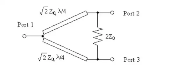
The Wilkinson power combiner architecture is used on Nuvotronics wideband combiners. In the basic Wilkinson structure, port 1 is the combined port, ports 2 and 3 are the input ports, and a single isolation resistor is connected across the input paths. Two-way combiners typically have two isolation resistors, and four-way combiners have up to six isolation resistors. Characteristic impedances of line segments vary throughout the combiner networks to form wideband impedance transformations.
3.1.1 Four-Way Wilkinson Combiner, 6–18 GHz (PSX12Q12W)
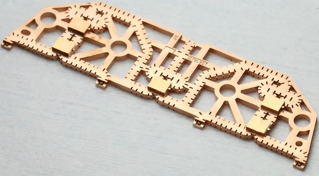
The PSX12Q12W is a four-way combiner covering 6 to 18 GHz. It is designed to be wire-bonded directly to power amplifier MMICs. The combined (output) port accommodates a pin launch to an external coax connector (not included). Screw holes sized for #2 screws (or metric M2) and alignment features sized for 1 mm diameter pins are provided for precise mounting to a substrate. Input ports are all in phase with respect to the output port; SSPA designers can use their own four-way divider design or use a second PSX12Q12W as a power divider.
3.1.2 Four-Way Wilkinson Combiner, 18–40 GHz (PSX29Q22W)
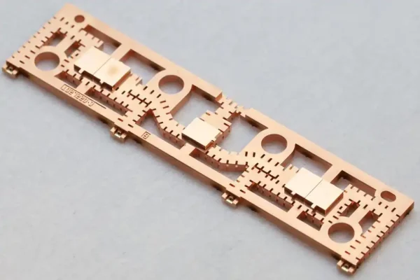
The PSX29Q22W is a four-way combiner covering 18 to 40 GHz. It is designed to be wire-bonded directly to the power amplifier MMICs. The combined (output) port accommodates a pin launch to an external coax connector (not included). Screw holes sized for #2 screws (or metric M2) and alignment features sized for 1 mm diameter pins are provided for precise mounting to a substrate. Input ports are all in phase with respect to the output port; SSPA designers can use their own four-way divider design or use a second PSX29Q22W as a power divider.
3.2 Gysel Combiners
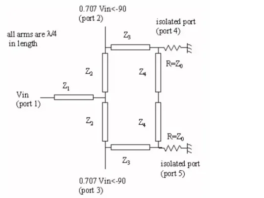
The two-way Gysel architecture used in Nuvotronics SatCom combiners comprises a ring of 1.5 wavelengths at center frequency, with shunt isolation terminations at two nodes. Four-way SatCom combiners are realized by cascading two-way Gysel combiners with fifty-ohm routing in between them.
3.2.1 Two-Way Gysel Quadrature Combiner, 37.5–42.5 GHz (PSX40D05W)
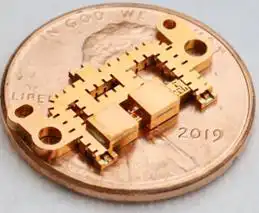
The PSX40D05W is a two-way combiner covering 37.5–42.5 GHz. Input ports are designed to be wire-bonded directly to power amplifier MMICs. The combined (output) port is also designed for wire bonding. Screw holes sized for #0 screws (or metric M1.6) and alignment features sized for 1 mm diameter pins are provided for precise mounting to a substrate. Input ports have been designed to have a 90° (quadrature) phase difference. Nuvotronics recommends pairing two PSX20D05W combiners, one used as a power divider, when combining two amplifiers to maintain correct phasing.
3.2.2 Two-Way Gysel Quadrature Combiner with Integrated 20 dB Directional Coupler, 37.5–42.5 GHz (PSX40D05V2W)
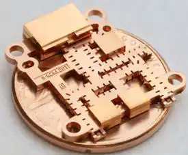
The PSX40D05V2W is a two-way combiner covering 37.5–42.5 GHz. Input ports are designed to be wire-bonded directly to power amplifier MMICs. The combined (output) port is compatible with standard rectangular waveguide that launches from the ground plane side of the part. The waveguide is back-shorted on top of the combiner output with a lid. The waveguide lid, terminating resistors, and resistor lids come pre-assembled on the combiner part. Screw holes sized for #0 screws (or metric M1.6) and alignment features sized for 1 mm diameter pins are provided for precise mounting to a substrate.
A 20 dB directional coupler is integrated into the combiner, with a wire bond interface. The coupled port is configured for use in monitoring output power (as opposed to reflected power) and may be left in an open-circuit condition without performance penalty. The opposite port of the directional coupler is internally terminated. Input ports have been designed to have a 90° (quadrature) phase difference. Nuvotronics recommends pairing the PSX40D05V2W combiner with the PSX20D05W (combiner without directional coupler) as a power divider when combining two amplifiers to maintain correct phasing.
3.2.3 Four-Way Gysel Combiners (PSX29Q03W and PSX50Q05W)
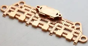
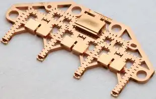
Nuvotronics four-way Gysel combiners include the PSX29Q03W, a 27.5 to 31 GHz design, and the PSX50Q05W, a 47.2 to 52.4 GHz design. These parts are designed to be wire bonded directly to power amplifier MMICs. The combined (output) port is compatible with standard rectangular waveguide that launches from the ground plane side of the part. The waveguide is back-shorted on top of the combiner output with a lid. The waveguide lid, terminating resistors, and resistor lids come pre-assembled on the combiner part. Screw holes sized for #2 screws (or metric M2) and alignment features sized for 1 mm diameter pins are provided for precise mounting to a substrate. Input ports are all in phase with respect to the output port; SSPA designers can use their own four-way divider design or use a second PSX29Q03W or PSX50Q05W as a power divider.
4. Mounting Considerations
Combiners discussed in this application note are designed to be integrated with high power amplifiers. If amplifiers fail or operate out of phase, a significant amount of heat will be dissipated in the combiner’s isolation resistors. The combiners are designed with high thermal conductivity materials that efficiently dissipate heat from the resistors to the surrounding PolyStrata copper ground structure. Mounting the combiner properly to a good heat sink is critical.
Every combiner part contains alignment hole and slot features to ensure optimal alignment to the end application substrate. Corrosion-resistant stainless steel dowel pins are typically press-fit into the next assembly substrate. Alternatively, gauge pins may be used for a slip-fit design where the pins are removed after assembly. Gauge pins are typically not offered in corrosion-resistant stainless steel, so they should be used for temporary alignment only and removed after assembly; they are also typically fabricated 2 inches long and need to be cut shorter for ease of use.
There are several methods to mount Nuvotronics combiners to a heat sink:
- Screws for a removable configuration
- Directly applied sintered silver or paste epoxy dots
- Custom preformed layer of sintered silver or conductive epoxy, cured within a holding fixture
- Solder (possible but not recommended)
4.1 Mounting with Screws
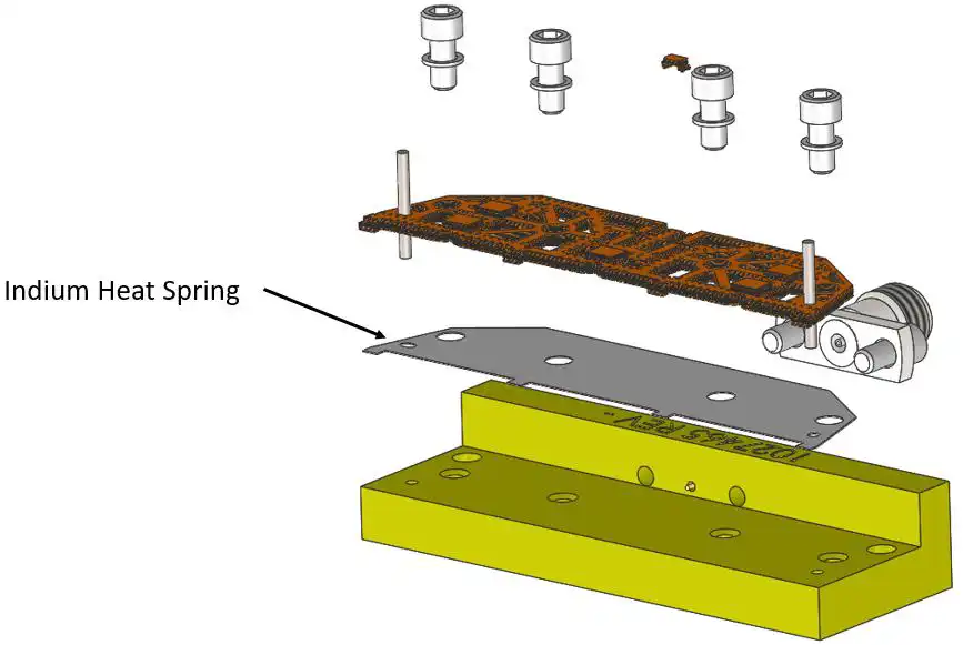
To avoid overheating, it is highly recommended to use a conductive interface such as Indium Corporation’s Heat Spring® foil between the ground plane of the combiner and the heat sink in the end application. Heat Spring has very low electrical resistivity (<10 µohm-cm) and high thermal conductivity (86 W/m-K), making it a good interface material for high power RF devices. It is a compliant foil made from high-purity indium that plastically deforms when screw-clamped between two substrates, and is patterned with small dimples that help take up small mismatches between surfaces. Heat Spring is typically offered in 0.004″ (100 µm) and 0.006″ (150 µm) thicknesses and can be easily laser cut, stamped, or knife cut to desired shapes. Refer to the Indium Corporation application note3 for more details on handling and use of Heat Spring foil.
- Cut or stamp the Heat Spring foil to the desired shape. Cubic Nuvotronics can assist with design of Heat Spring foil preforms, including integrated alignment hole and slot features — particularly important for combiner parts with a waveguide combined port to ensure optimum waveguide opening alignment.
- Place the foil down onto the heat sink.
- Use screws to attach the combiner on top of the foil. Screw pressure provides a robust thermal and electrical ground. Screws should be installed “finger tight” first and then torqued to spec. Washers up to 0.188″ (4.8 mm) outside diameter are recommended to help distribute the fastener load and prevent damage to the combiner surface.
| Screw | Torque, in-oz (cN-m) |
|---|---|
| #0 | 19 (14) |
| #2 | 57 (40) |
4.2 Mounting with Directly Applied Sintered Silver or Paste Epoxy
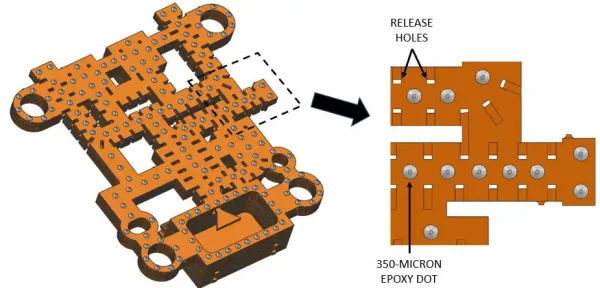
Combiners can be permanently attached to a heat sink using a conductive silver paste epoxy such as Henkel 84-1LMIT1 or, for higher conductivity, sintered silver such as Namics H9890-6. This can be accomplished using auto or manual dispense, jetting, or stencil methods.
- Place sintered silver or epoxy dots across the entire surface, approximately centered between release holes.
- Flip the part over and place it onto the end application substrate using pin alignment.
- Apply gentle pressure to squeeze out the epoxy dots.
- (Optional) Screws may be installed while the epoxy is wet, prior to oven cure, or after epoxy cure.
- Cure the epoxy.
4.3 Mounting with Preform Epoxy or Sintered-Silver Film
Nuvotronics commonly uses Henkel 5025E conductive film preforms to attach PolyStrata parts to substrates. Film preforms are easier to assemble than pastes because they can be handled without concern of epoxy smearing. However, constant pressure is typically required during oven cure of the preform, which requires a custom mounting fixture set.
A typical custom mounting fixture set uses a base fixture to hold the end application substrate (housing, PCB, or similar) in position. A bridge fixture screw mounts to the base fixture and has stainless steel spring plungers threaded into it. The ball-nose ends of the spring plungers touch down against a flat pressure plate, which applies down force to the PolyStrata part/preform/substrate sandwich. The pressure plate should have relief pockets to avoid contacting the lids (resistor, waveguide) on the combiner part.
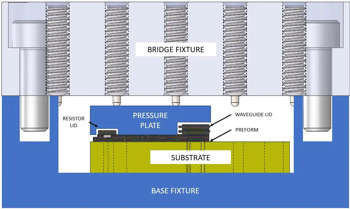
The spring plungers should be distributed approximately evenly over the area of the pressure plate and PolyStrata part. Use the preform manufacturer’s datasheet to obtain the curing pressure recommendation, then calculate the plunger quantity and number of turns of each plunger to achieve the recommended pressure (pressure equals total force divided by attach area). The attach area of the combiner part can be obtained from the 3D model, provided upon request. Cubic Nuvotronics can assist with the design of custom pressure-cure fixtures and epoxy preforms.
4.4 Mounting with Solder
Solder is not recommended but may be used with a few caveats. PolyStrata parts are necessarily designed with small “release holes” that go through the ground walls of the part into the RF coax structures, enabling removal of resist material from internal coax volumes to provide the air dielectric that makes PolyStrata parts uniquely high-performing. During reflow, solder can wick uncontrolled across the copper ground plane; because release holes have no solder stops, solder can also wick into the RF coax space and potentially degrade combiner performance. For additional information, consult Nuvotronics’ “General Guidelines for Handling PolyStrata Components.”1 Care must also be taken with bare copper PolyStrata parts to sufficiently deoxidize the copper prior to soldering.
5. RF Interconnects
RF output interconnects depend on which combiner is being considered.
5.1 Waveguide RF Output (Gysel Combiners)
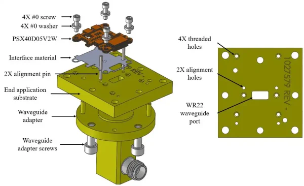
The end application substrate for a typical Gysel combiner packaging embodiment may be a machined housing or a type of circuit board. Threaded mounting holes, alignment holes, and WR22 waveguide slot features are designed into the substrate. The alignment holes and pins should be used to precisely align the WR22 waveguide port in the combiner part to the waveguide port in the end application substrate. The interface material, coupled with the mounting screws, forces intimate electrical and thermal contact between the ground plane of the combiner (including the WR22 waveguide port) and the mating features in the substrate. A COTS waveguide adapter aligns and screw-mounts to the opposite side of the substrate. A lid over the entire combiner part may be designed into the end application to help with isolation and reduce EMI. Models and drawings of generic end-application packaging environments for all combiner products are available upon request, and Cubic Nuvotronics can assist with end-application packaging design.
5.2 Coaxial RF Output Connectors (Wilkinson Power Combiners)
PSX12Q12W and PSX29Q22W parts are designed to accept a coaxial pin at the combined port. The PSX12Q12W is designed for a 0.015″ diameter launch pin; the PSX29Q22W interfaces to a 0.012″ diameter pin.
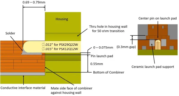
The launch pin should be centered over the launch pad, with a small gap (up to 0.075 mm) designed in between the bottom of the pin and the launch pad for assembly clearance. The pin should be centered in the housing hole and extend 0.69 to 0.79 mm (0.027″ to 0.031″) beyond the housing wall, allowing sufficient overlap length with the combiner launch pad for interconnection. It is recommended to solder the pin to the combiner launch pad for optimum reliability, using gentle force when touching down on the launch pad manually with solder wands — the launch pad is supported on the underside by a ceramic seat that may fracture under excessive down-force. It may also help to place the assembly on a hot plate at 100°C to elevate the temperature of the entire assembly during this soldering step.
Eight-step process for attaching the combiner to a coaxial pin:
- Align and place Heat Spring foil to the housing.
- Prior to mating the combiner to the housing, apply conductive epoxy to the side face of the combiner around the pin. This epoxy provides the ground between housing and combiner around the signal pin and should be applied sparingly — enough to contact the housing wall without significantly intruding into the air coax region.
- Place the combiner on the housing floor and slide the launch pad under the pin. Mate the combiner flush against the housing wall to ensure an epoxy bridge between the housing wall and the combiner pin launch region.
- Screw the combiner down. Alignment pins may help hold the combiner in position as the screws are installed. The epoxy can be cured now or at the end of the process.
- Solder the pin to the launch pad. The coaxial pin is designed to be lidded for a 50-ohm transition; the lid is included with the combiner part and is installed by the user after the pin is soldered to the launch pad.
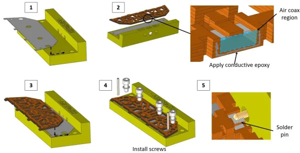
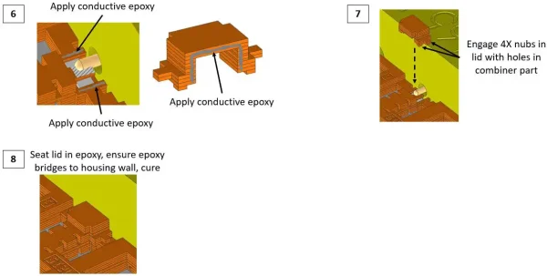
- Sparingly apply epoxy in preparation for lid attachment.
- Align and engage the nubs on the lid with the holes in the combiner part, and seat the lid in the epoxy so the pre-applied epoxy paste bridges from combiner part to lid to housing wall.
- Cure the epoxy.
5.3 Amplifier Interconnects (Wire Bonding)
The design detail in this section should be treated as a guideline, as there are many unique packaging embodiments and tolerances associated with chip-and-wire hybrids. Nuvotronics recommends users perform their own RF simulations to ensure wire bond performance specifications are achieved in the end application.
The wire bond launch is common across every combiner part and comprises an integrated alumina chip with PolyStrata-defined copper ground-signal-ground (GSG) traces and a gold wire-bondable surface finish. The GSG launch is designed to be thermosonically bonded to gold interconnect wire. Nuvotronics has performed RF simulation to tune the wire bond launch for operation up to about 50 GHz. Optimum RF performance might require modifying the wire bond geometry depending on what the MMIC expects for wire bond inductance; Cubic Nuvotronics will provide an HFSS model of the interface upon request.
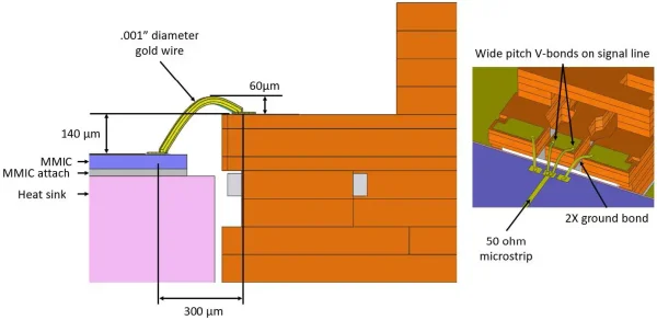
The simulated MMIC in the wire bond transition design has gold GSG pads and expects a 50-ohm interface inside the signal pad. The two ground pads each have through-vias tied to ground on the bottom side of the MMIC. Two wires are bonded with a wide pitch to the signal line on the PolyStrata launch; the signal wires have a 60 µm loop height and traverse 140 µm down to the signal pad on the MMIC, forming roughly a “V” shape when bonded. The bond pad to bond pad distance is 300 µm. There is one ground wire per pad with the same loop height as the signal wires, biased to the inboard (signal) side on the PolyStrata launch to allow clearance of the wedge tool to the copper shield on both sides of the ground pads. Cubic Nuvotronics simulations show the two ground bonds are optional at operating frequencies below 30 GHz.
6. References
- “General Guidelines for Handling PolyStrata® Components,” Cubic Mission & Performance Solutions, 3 November 2022. cubic.com
- “Diamond RF Resistives® Family,” Smiths Interconnect. smithsinterconnect.com
- “Use of Heat Spring,” Application Note, Indium Corporation. indium.com
7. Revision Log
| Rev | Date | ECN | Comment |
|---|---|---|---|
| – | 04/10/24 | ECN1008744 | Initial Release |
| A | 01/13/25 | ECN1009313 | Fix error in Figure 13 |